


Overview of this 4-20ma to 5v converter for arduino industrial sensor interface board
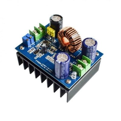
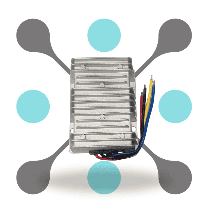
Introducing roboway 4-20ma to 5v converter for arduino industrial sensor interface board at best price for interfacing industry sensors with microcontrollers. This board simplify the complex task of converting current signals (4-20mA or 0-20mA) to analog voltage output (0-5V or 0-3.3V or 0-10V). And make it easy to connect to the ADC pin of your microcontroller.
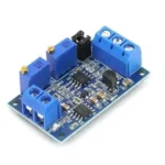
With its onboard screw terminal connectors, this interface board offers easy and simple connections. And eliminate the need for external circuit and tuning. It also feature a wide supply voltage range of 7-36V & ensure compatibility with various power source. And this board also provide high stability, good linearity, and industry grade performance.
Equipped with adjustable zero and range settings, as well as reverse polarity protection, this converter board offers flexibility and reliability in industrial applications. Its high precision color ring resistance ensures accurate current signal sampling, making it suitable for demanding industrial environments.
Feature
- Industrial Sensor Interface: It easily interface with Arduino/Raspberry Pi with industrial sensors/devices using 4-20mA output. And also Simplify complex conversions, eliminating external circuits and tuning requirements.
- Voltage Output: Converts 4-20mA (or 0-20mA) current signal to selectable 0-5V, 0-3.3V, or 0-10V analog voltage. Directly connects to microcontroller ADC pins for easy integration and signal processing.
- Wide Supply Voltage Range: It also support supply voltage from 7V to 36V & ensure compatibility with various power source. And provide flexibility in power option for different use.
- Adjustable Zero and Range: Allows adjustment of zero and span via potentiometers for precise output calibration. Ensures accurate voltage output corresponding to input current signals.
- High Stability and Linearity: Industrial-grade construction ensures high stability and good linearity for reliable performance. Ideal for demanding industrial applications requiring precise signal conversion.
- Multiple Voltage Ranges: Offers multiple voltage output ranges to suit different application requirements. Enhances versatility and compatibility with a variety of microcontroller projects.
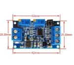
- Compact and Lightweight: Compact design with onboard screw terminal connectors for easy and simple connections. Lightweight module weighs only 12g, facilitating installation and integration into projects.
Specification
| Specification | Description |
|---|---|
| Input Signal Range | 4-20mA |
| Output Voltage Range | 0-5V |
| Accuracy | ±0.1% |
| Resolution | 12-bit |
| Isolation | Galvanic isolation between input and output |
| Supply Voltage | 5V DC |
| Operating Temperature Range | -40°C to +85°C |
| Response Time | <10 ms |
| Input Impedance | 250 Ohms |
| Output Load Resistance | 10 kOhms |
| Power Consumption | <20 mA |
| Dimensions | Compact form factor for easy integration |
| Interface | Analog voltage output compatible with Arduino |
| Protection | Overcurrent protection, reverse polarity protection |
| Mounting Options | Through-hole or surface mount options available |
| SKU | RW-526 |
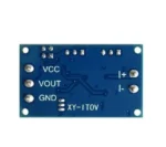
- The module according to the definition of wiring, power supply voltage 7-36V (if the output to 10V, the supply voltage must be greater than 12V).
- After power-up, the D2 indicator should be on, otherwise check the line connection. Board with reverse protection, the reverse does not burn.
- When the current input is the minimum (0mA or 4mA), adjust the ZERO potentiometer so that the VOUT output is the minimum (0.0V or other voltage).
- When the current input is at maximum (20mA), adjust the SPAN potentiometer so that the VOUT output is the maximum (3.3V or 5V or 10V, the output can be as low as 2.5V when the input is 4-20ma).
- According to your needs, through the jumper cap to select the appropriate range:
Jumper Settings for Output Voltage Range Input Signal: 4-20mA
- 1.0-2.5V: J1 1,2 pin are short circuit connection; 3, 4 pin are short circuit connect
- 2.0-3.3V: J1 1,2 pin are disconnect; 3, 4 pin are disconnect
- 3.0-5V: J1 1,2 pin are short circuit connect; 3, 4 pin are short circuit connect
- 4.0-10V: J1 1,2 pin are short circuit connect; 3, 4 pin are disconnect
Jumper Settings for Output Voltage Range Input Signal: 0-20mA:
- 1.0-3.3V: J1 1,2 pin are short circuit connected; 3, 4 pin are short circuit connected
- 2.0-5V: J1 1,2 pin are short circuit connected; 3, 4 pin are short circuit connected
- 3.0-10V: J1 1,2 pin are short circuit connected; 3, 4 pin are disconnected


Reviews
Clear filtersThere are no reviews yet.