DC DC Converter

What is DC DC Converter

A DC to DC Converter is a device which is use to convert direct current(DC) voltage from a level to another desired level. It take a DC current from input source and provide a controlled voltage of dc current. It is generally use in many industrial commercial, vehicle, & mobile device which works on DC input current.

Use of DC Power converter

Dc Dc power module are use at many place or device which works on stable dc input range. And it Is also use to Control DC Voltage input range in many device. Here are some use of Dc converter in everyday life.

main uses of dc dc converter by roboway
Power Electronic Devices:
  • DC Converter are also use to power electronic device such as Smart phones, laptop, & other portable device. And provide control voltage require for smooth function of device. These power Module also help for high efficiency & performance of electronic devices.
Renewable Energy system:
  • DC Power module play a critical role in renewable energy systems. It is use to optimize power conversion from solar panel to battery charging system. And also use for same function in wind mill energy system for smooth power conversion.
Vehicle electronics:
  • DC DC power module also use to provide desired voltage to vehicle electronics like sensors, lights, & control systems. And it is also use in battery charge systems for smooth charging at stable DC input.
Industry Device:
  • It is also use to power many Industry device. And support in industry automation system for high & smooth performance. It is also use to provide controlled power for sensitive device in manufacturing department.

Telecommunication system:

  • DC DC power module use as an important device in telecommunication device for smooth & stable communication system. It is mainly used to power base station, network device, and data center which work on DC input.
Medical device:
  • Dc-Dc Module use to power various medical device including, MRI machine, monitor device, & portable medical device. And also ensure a smooth & stable power supply for critical medical device.

Working Principle Of DC Converter

The Working principle of a dc-dc converter involve conversion of a DC voltage from a level to another specific level. And also maintain a stable output Voltage. There are several type of DC module with its specific working principle. This working principle of Dc Dc power module include various function of different device.

Circuit diagram of dc dc converter

  • Input Voltage regulation: This Input voltage is provide by various dc power source like battery, solar panel.
  • Switching element control: Every dc converter a switch element like transistor or mosfet which work as a switch. These switch element is control by pulse width module(PWM) a signal generate by circuit.
  • Inductor or capacitor for storage: when switch element is turned on then dc current is to inductor or capacitor. At same time a Diode stop it to flow back to input source.
  • Energy transfer: After switch element is off the magnetic field around inductor destroy. This stored voltage & input voltage applied to load dc current. And at same time capacitor help to provide a stable dc output for smooth performance.
  • Output voltage control: The duty cycle of pulse width modulation help to control of output voltage & provide stable output. By adjusting duty cycle of PWM we can get desired level of output voltage.
  • Feedback Control: Many DC-DC converters also include feedback control system to monitor the output voltage and adjust the PWM signal based on need. This feedback loop ensure that the output voltage remains stable and within the desired range.

Overall, the working principle of DC-DC converter is switch the input voltage on and off at a high frequency & control the output voltage by controlling the duty cycle of the PWM signal. This process allows for smooth power conversion and voltage control across a wide range of device.

Types of DC DC Converter

There many types of dc dc converter based on device need. Here are main general types of dc dc converter. Buck Converter (Step-Down Converter), Boost Converter (Step-Up Converter), Buck-Boost Converter, Flyback Converter, Forward Converter, Cuk Converter, SEPIC Converter, Charge Pump Converter. Buck converter, Boost converter, Buck-boost converter are most used Power modules across Industry.

DC DC Buck Converter (Step-Down Converter)

 A Buck Converter is also known as step-down converter which is use to Convert as specific range of dc voltage from a high voltage to lower voltage. It is also use in multiple electronic device which work on stable lower dc voltage.

Use of Buck converter (Step-down converter)

Buck converter is use at many place which need stable lower dc voltage. Here are some main use of dc dc buck converter (step down converter).

Power supplies:-  Step down converter is also use mostly used in power supply to step down high voltage to stable lower DC voltage. It is generally used in electronic device like computer, electronic device, mobile charger & other dc device.

Voltage Converter:- Buck converter is also use for voltage control in various electronic device. And make sure a safe & stable dc voltage supply to sensitive electronic device.

Solar Power Systems:-  Buck converter is also use in solar power system to smoothly convert higher dc voltage to stable output for battery charging. They play an important role in to increase the energy collected from solar panels with high system efficiency

LED Lighting:- Buck converters are also use in LED light system to control the voltage and current supply to the LED. This helps achieve stable brightness levels & improve energy efficiency, and extend the lifespan of the LED.

Working principle of dc step-down or buck converter

The working principle of a DC step-down converter, also known as a Buck converter. And involve smoothly reduce a higher input voltage to a lower output voltage. Here's a step by step explanation of its operation:

Input Voltage:  First step of Step down dc conversion is to take input voltage from dc source. It may take input voltage from dc battery or solar source or any other DC source.

Circuit diagram of dc dc step down or buck converter

Switching stage: The heart of buck converter a switch element(mosfet) that turn on & off quickly. And this switch element use control by Pulse width module(PWM) a signal generate by control circuit of convertor.

Inductor: The Buck converter include an inductor in circuit. Main function of this inductor is to store energy in its magnetic field. When the circuit is switched on then current flow through inductor, & energy in store in its magnetic field. And Inductor resist change in current & make it stable.

Diode:  In some step down converter circuit diode is use parallel with load. This diode provide when circuit Is off path for energy store in inductor magnetic field & ensure regular current flow for dc current.

Output capacitor: An output capacitor is used to filter the output voltage and reduce any remaining ripple or fluctuations. It also helps to provide a stable and regular output voltage to the load.

Control circuitry: Some buck converter also use control circuit which include feedback system. That watch duty cycle of switching element to maintain a stable output voltage.

Output voltage control: By controlling the duty cycle of the switching element, the buck converter effectively reduces the input voltage to a lower output voltage. The output voltage is regulated based on the input voltage, duty cycle, and other circuit parameters.

Boost Converter

A DC-DC step up module is a type of power electronic circuit used to step up a lower dc input voltage to a higher dc output voltage. It's commonly used in various applications where a higher voltage than the input voltage is required.

Working principle of Step up/boost converter

Input Voltage: The dc boost converter take input voltage from a dc source like battery or any other power source.

Switching element(Transistor):

Similar to buck converter boost converter also contain a switching element(mosfet). Main function of this transistor is to switch on & off circuit fast based on specific duty cycle.

Inductor:

The boost converter contain an inductor in circuit when the transistor is switched on current flow through inductor & energy stored in its magnetic field. This Inductor is connected in series connection with load & input Voltage.

Roboway circuit diagram of dc dc boost converter or step up power module

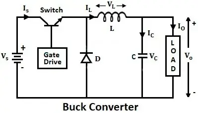
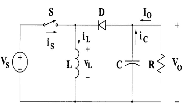
Diode: A Diode is connected in parallel connection with load. When switch element is off then stored energy is released & bypass the input voltage to load.

Output capacitor: An Output capacitor is used to filter the output voltage & reduce any ripple fluctuation.

Duty cycle control: The duty cycle of switching element determine the ratio of time of off state & on state circuit. In Boost converter duty cycle is always greater than 50%.

Output Voltage regulation: A Voltage regulator is use in boost converter (Step-up dc dc convertor) circuit to maintain a stable out put voltage. In dc dc boost converter as duty ratio increase output voltage also increase.

Mainly duty cycle ratio is main feature which make it boost convertor or buck convertor. When duty cycle ratio Is more then 50% then converter act as a boost converter & when it is less then 50% it act as buck converter.

Main Use of Step-up Converter

The main use of a step-up converter, also known as a boost converter, is to increase a lower input voltage to a DC higher output voltage. Here are some of the main use of step-up dc dc converters:

Battery powered device: Boost converter are generally used in battery powered device where battery output voltage is lower then needed voltage. So boost converter use to increase dc input as per device need.

LED Light: Boost converters are also use in LED light device. LEDs generally need a higher forward voltage than the voltage provided by the power source. Boost converters step up the voltage to fulfill the need of the LEDs. And allow for smooth and stable light solution in various device such as vehicle lights, signage, and backlights.

Solar power system: Boost converter (step up converter) is also use in solar power system to maintain a stable dc voltage from a lower dc source.

HVAC Systems: Heating, Ventilation, and Air Conditioning (HVAC) systems also need higher voltage for certain components such as motors and control circuit. Boost converters use in HVAC systems to boost the voltage from the power source to meet the need of these component.

What is Buck-Boost Converter

A dc converter is a type of power converter which can step up or step down dc voltage to a specific voltage. Unlike buck converter or boost converter it can use for dual function of buck or boost module.

Working principle of Buck-boost Converter

The working principle of a DC-DC buck-boost module involve control of the output voltage to a desired level. Whether the input voltage is higher or lower than the needed output voltage. This makes the buck-boost converter highly versatile, as it can both step up (boost) and step down (buck) input voltages. Here's a detailed explanation of working principle of dc dc buck-boost converter:

Roboway circuit diagram of dc dc boost converter or step up power module

Buck operation (Step-down):

In Buck operation when the switch in on current flow through the  inductor which is connected in parallel series. And energy is stored in inductor in form of magnetic wave.

And when switch element is off inductor release stored energy to diode. And energy stored in inductor transfer to load.

During this phase duty cycle is always lower then 50% hence this process is known as buck converter.

Boost operation (Step-up):

In boost operation when switch is current flow through the inductor which is connected in series connection. And when it is switched off then current is flow through load.

During this phase duty cycle is always more then 50% hence this process is known as buck converter.

Control mechanism:

 The duty cycle of the switch is controlled to regulate the output voltage. By adjusting the duty cycle, the average voltage delivered to the load can be controlled.    

Feedback mechanisms such as voltage regulation circuits are use to adjust the duty cycle based on the difference between the desire output voltage and the actual output voltage.

Uses of dc buck-boost converter

A DC-DC buck-boost converter is a best converter for multiple electronic devices. Main use of dc-dc buck converter to provide a stable dc voltage either input voltage is higher or lower than the needed voltage. Here are some main use of dc dc buck boost converter.

  1. Battery power Electric device: Buck- boost converter is also use in many battery powered device where battery out put can change. And it provide a stable dc output voltage for smooth function of connected device.
  2. UPS Power supply: Buck-boost converter also use as an important device in UPS system to maintain as stable power for connected device when input voltage change. Buy control on UPS stable output voltage it also provide safety for connected device.
  3. Portable Medical device: It is also use in portable medical device like infusion pump, & other diagnostic device. Buck-boost converter also ensure a stable voltage input for critical device.
Here are some most used dc converter in industry automation & DIY project.

Leave a Reply

Your email address will not be published. Required fields are marked *